Product Overview
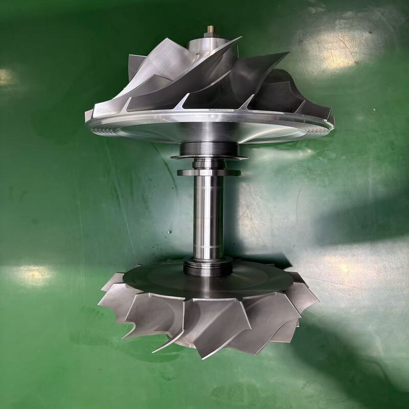
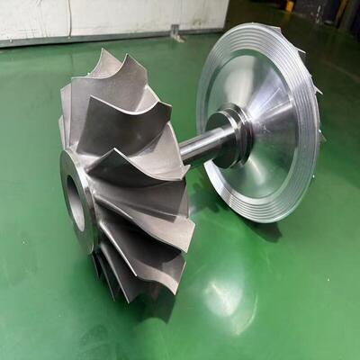
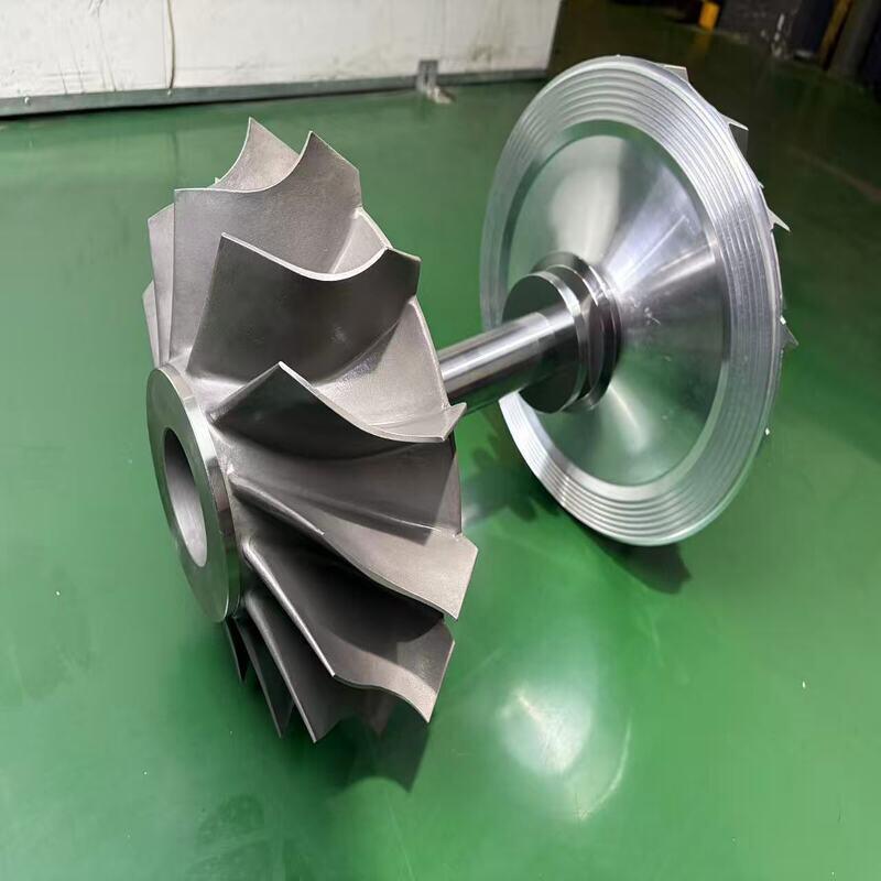
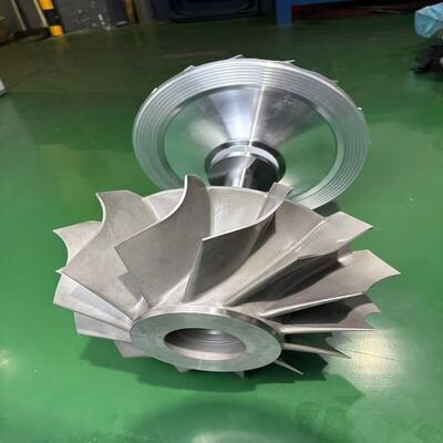
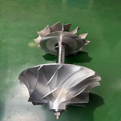
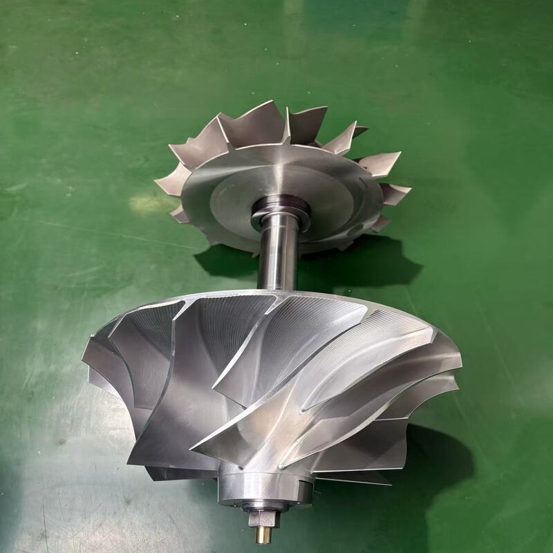
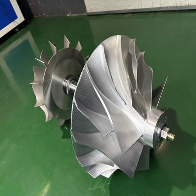
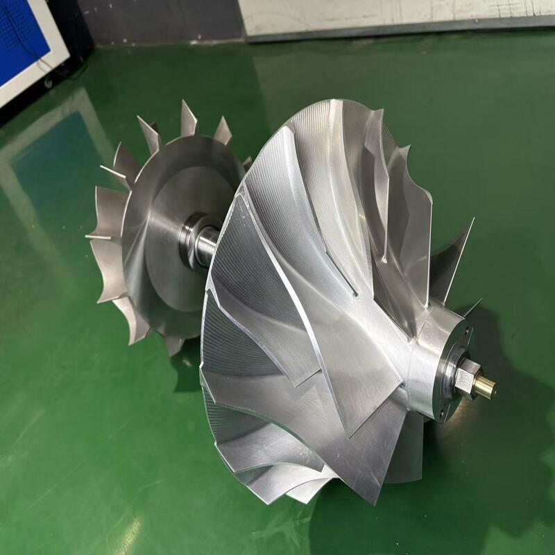
Our high-speed balanced rotor complete assembly is a ready-to-install rotating unit engineered for demanding motor and turbine applications. It integrates the rotor core, precision-ground shaft, pre-mounted bearings, and balancing elements into one factory-tested assembly. Every unit is dynamically balanced to ISO G2.5 or better, verified at operating speed to guarantee ultra-low vibration, extended bearing life, and consistent output. Made from high-grade electrical steel and alloy shaft materials, the rotor complete assembly minimizes assembly errors, eliminates on-site balancing, and reduces maintenance downtime. Suitable for AC/DC electric motors, steam turbines, gas turbines, and high-speed spindles, this assembly is tailored to your torque, speed, and mounting requirements. Whether you need a standard replacement or a custom-engineered rotor, our one-piece rotor complete assembly delivers predictable performance and faster commissioning. By integrating core and shaft with rigorous balancing, we help you achieve higher efficiency, lower noise, and reduced total cost of ownership. All assemblies undergo dimensional inspection, surface finish check, and dynamic runout test before shipment, ensuring immediate usability in your production line.
Cause
Imbalanced or poorly assembled rotor systems are a leading cause of vibration, bearing damage, and unexpected machine stoppage. When a rotor is sourced as separate components and assembled on site, variations in fit tolerance, alignment, and balancing accuracy frequently introduce eccentricity and mass unbalance. This generates excessive radial forces, leading to premature bearing wear, seal leakage, shaft fatigue, and even structural resonance. In motor and turbine applications, even slight unbalance can result in energy loss, overheating, and amplified noise. Maintenance teams often struggle with inconsistent replacement rotors that require time-consuming trial fitting and repeated balancing attempts. These challenges increase operational risk, drive up spare parts inventory, and extend machine downtime. Without a complete, pre-balanced rotor assembly, achieving repeatable high-speed stability and long-term reliability is significantly harder, especially under variable load and continuous duty cycles.
Solution
We solve these problems by supplying fully integrated rotor complete assemblies that are dynamically balanced and 100% tested before dispatch. Rather than delivering loose shafts, laminations, and bearings, we assemble, align, and balance the entire rotating unit under controlled factory conditions. The rotor core is shrink-fitted or keyed onto the shaft, bearings are mounted with specified preload, and the assembly is balanced on a precision balancer at operational speed or a validated equivalent speed. This approach eliminates on-site assembly variability, guarantees concentricity, and ensures residual unbalance stays within ISO G2.5 or user-specified limits. Because each rotor complete assembly arrives turnkey, your team simply installs it into the stator or housing, reducing commissioning time by up to 70%. We also offer custom engineering support—materials, coatings, cooling features, and shaft extensions can be adapted to your equipment. With batch traceability, certified balance reports, and dimensional conformance documents, our rotor complete assemblies give you repeatable quality and lower total lifecycle cost, making them ideal for both OEM production and MRO replacements.
Specifications
| Parameter |
Details |
| Rotor Type |
Squirrel cage, wound rotor, permanent magnet rotor, turbine disc rotor |
| Core Material |
50W470 / 50W600 / 35W250 electrical steel, custom grades available |
| Shaft Material |
42CrMo, 40Cr, 304/316 stainless steel, alloy steel |
| Outer Diameter Range |
80 mm – 1500 mm (standard), larger on request |
| Shaft Diameter Range |
20 mm – 300 mm |
| Core Length |
100 mm – 3000 mm |
| Balancing Grade |
G6.3, G2.5, G1.0 (ISO 1940-1) |
| Maximum Operating Speed |
Up to 30 000 RPM (depending on diameter) |
| Bearing Seat Tolerance |
H7/k6 or per drawing |
| Runout (Shaft & Core) |
≤ 0.02 mm |
| Balancing Method |
Two-plane dynamic balancing with correction by drilling, milling, or weight addition |
| Testing & Documentation |
Balance report, dimensional inspection report, material certificate |
| Customization |
Keyway, cooling ribs, radial ventilation ducts, coatings, shrink disc interface, sensor targets |
| Packaging |
Export-grade wooden crate with anti-corrosion protection |
Application
-
High-speed and medium-voltage electric motors
-
AC/DC industrial motors and servo motors
-
Steam turbines and gas turbine auxiliary drives
-
Turbocharger rotor modules
-
Centrifugal compressors and blowers
-
High-speed spindles for machine tools
-
Permanent magnet generator rotors
-
Traction motors for rail and electric vehicles
-
Pump rotors for high-pressure multistage pumps
-
Any rotating equipment requiring a ready-balanced rotor core-and-shaft unit
How It Works
A rotor complete assembly converts electromagnetic or fluid energy into mechanical rotation. In electric motors, the laminated rotor core carries conductors or permanent magnets. When the stator generates a rotating magnetic field, it induces current in the rotor conductors, creating electromagnetic torque that spins the rotor and its integrated shaft. In turbines, high-pressure gas or steam impinges on blades fixed to the rotor disc, driving the shaft directly. The shaft, supported by bearings, transmits torque to the coupled load. Because the core, shaft, and bearings form one rigid, balanced assembly, the rotating mass remains stable even at high speed. The balancing process compensates for residual mass asymmetry, minimizing centrifugal forces and vibration. Pre-mounted bearings with correct clearance and preload ensure smooth rotation and lower friction. Cooling features, such as radial ducts or integral fan blades, may be incorporated to manage thermal expansion and keep the rotor within safe temperature limits, preserving air gap uniformity and preventing thermal bowing. This integrated design ensures efficient power transmission, lower noise, and longer operating life under continuous duty.
How To Choose
-
Define your machine parameters: Know the rated power (kW), rated speed (RPM), and supply frequency (Hz) of your motor or turbine.
-
Determine the rotor type: Choose squirrel cage for robust induction motors, wound rotor for slip control, permanent magnet for high-efficiency synchronous machines, or turbine disc for turbine drives. Provide the original manufacturer’s drawing or code if possible.
-
Select core and shaft materials: Match the electrical steel grade to your efficiency target and thermal class. For corrosive or high-temperature environments, request stainless steel or alloy steel shafts.
-
Specify mechanical interfaces: Confirm shaft diameter, keyway dimensions, bearing journal size, and bearing type/designation. Indicate any coupling flange, shrink disc, or encoder mounting requirements.
-
Set balancing requirements: For high-speed applications (above 3000 RPM), specify ISO G2.5 or G1.0. For general industrial motors, G6.3 may be acceptable. Tell us the maximum operating speed and whether two-plane balancing is needed.
-
Address cooling and protection: If the rotor operates in a sealed or high-ambient environment, discuss internal cooling ducts, shaft-mounted fans, or anti-corrosion coatings.
-
Request documentation: Confirm you need a balance report, material certificate, and dimensional inspection record for your quality system.
-
Sample and prototype: For OEM projects, we can provide a prototype rotor complete assembly for testing and validation before series production.
-
Contact our engineers: Send your specifications, drawings, or a completed inquiry form. We will propose a verified design, lead time, and quotation within 24 hours, ensuring you get a rotor complete assembly that fits directly and runs smoothly.
FAQ
1. What is a rotor complete assembly and how does it differ from a bare rotor core?A rotor complete assembly is a fully integrated unit that includes the rotor core, shaft, bearings, and balancing components, all factory-assembled and dynamically balanced. A bare rotor core is just the laminated magnetic core without shaft, bearings, or balancing. Using a complete assembly eliminates on-site assembly errors and balancing work, saving installation time and improving reliability.
2. What balancing grade can you achieve for high-speed rotors?We routinely balance to ISO G2.5 and, for critical high-speed applications such as turbine rotors and spindles, we can reach G1.0. Each assembly is balanced at operational speed or a speed calculated to represent the service condition, and a certified balance report is provided with every shipment.
3. Can you manufacture a rotor complete assembly from a sample or drawing?Yes. We specialize in custom and replacement rotor assemblies. Provide your original drawing, a reverse-engineered specification sheet, or a physical sample, and our engineering team will replicate the design with exact mechanical interfaces and performance characteristics. We also suggest material or balancing improvements if needed.
4. What is the typical lead time for a custom rotor complete assembly?Standard replacement assemblies with common materials usually ship within 4–6 weeks. Complex custom engineered rotors with special materials, coatings, or unique shaft geometries may take 8–12 weeks. We provide a firm delivery schedule at quotation stage and keep safety stock for repeat orders.
5. How do you guarantee the quality and concentricity of the assembly?Every rotor complete assembly goes through shaft runout measurement, core concentricity check, dynamic balancing, and a final dimensional inspection. We use CMM, dial indicators, and precision balancing machines. Tolerance reports and material certificates are included, ensuring that the assembly meets or exceeds the print specifications before it leaves the factory.

 Il tuo messaggio deve contenere da 20 a 3000 caratteri!